Skip to content
Email
Tel
whatsapp
Search
Youtube
Linkedin
Facebook
Tiktok
Twitter
Email
Tel
whatsapp
Search
Tiktok
Twitter
Youtube
Linkedin
Home
Products
Dust Collection System
Bulk Loader System
Conveying System
Cement Grinding
Cement Silo System
Valve
Spare Parts
Air slide fabric
Belt Conveyor Roller
Expansion Joint
Filter Bag
Dust Collector Filter Bag
Cases
News
About Us
Industries We Serve
Company Profile
Contact Us
English
Japanese
Spanish
Arabic
Portuguese
French
Russian
Search
Search
Home
>
2024
CONATCT
MORE+
Tel: +86-15370455293 +86 15365564889
Email: sales@darko-tech.com
24-hour hotline: +86 15370455293 +86 15365564889 ( WhatsApp )
Mining Dust Collector Selection Guide
Optimization of the Clinker Bulk Loader Discharge Structure
Analysis of Air Leakage in Cement Kiln Systems
Optimizing Bag Filter Systems: Key Dust Hood Design Elements
Single Machine Bag Dust Collector Installation Guide
Bag Filter Dust Collector Cooling Measures
Differences and Applications of On/Off and Regulating Electric Butterfly Valves
U-type Screw Conveyor: Efficient Transport Solution
Corrosion Causes and Prevention in Flue Gas Desulfurization Systems
Maintenance Guide for Clinker Bulk Loader
Boiler Bag Dust Collector Renovation Case
How to Effectively Handle Workshop Dust?
<
>
2024
Take a break and read all about it
News
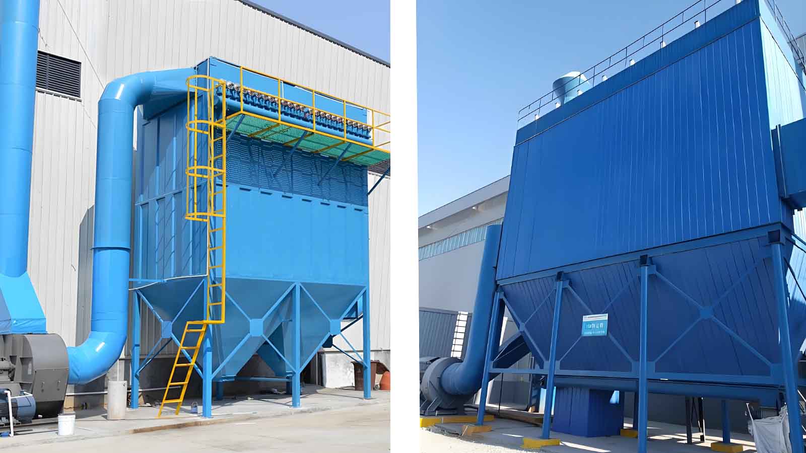
Mining Dust Collector Selection Guide
2024-12-31
News
Optimization of the Clinker Bulk Loader Discharge Structure
2024-12-30
News
Analysis of Air Leakage in Cement Kiln Systems
2024-12-27
News
Optimizing Bag Filter Systems: Key Dust Hood Design Elements
2024-12-26
News
Single Machine Bag Dust Collector Installation Guide
2024-12-25
News
Bag Filter Dust Collector Cooling Measures
2024-12-23
News
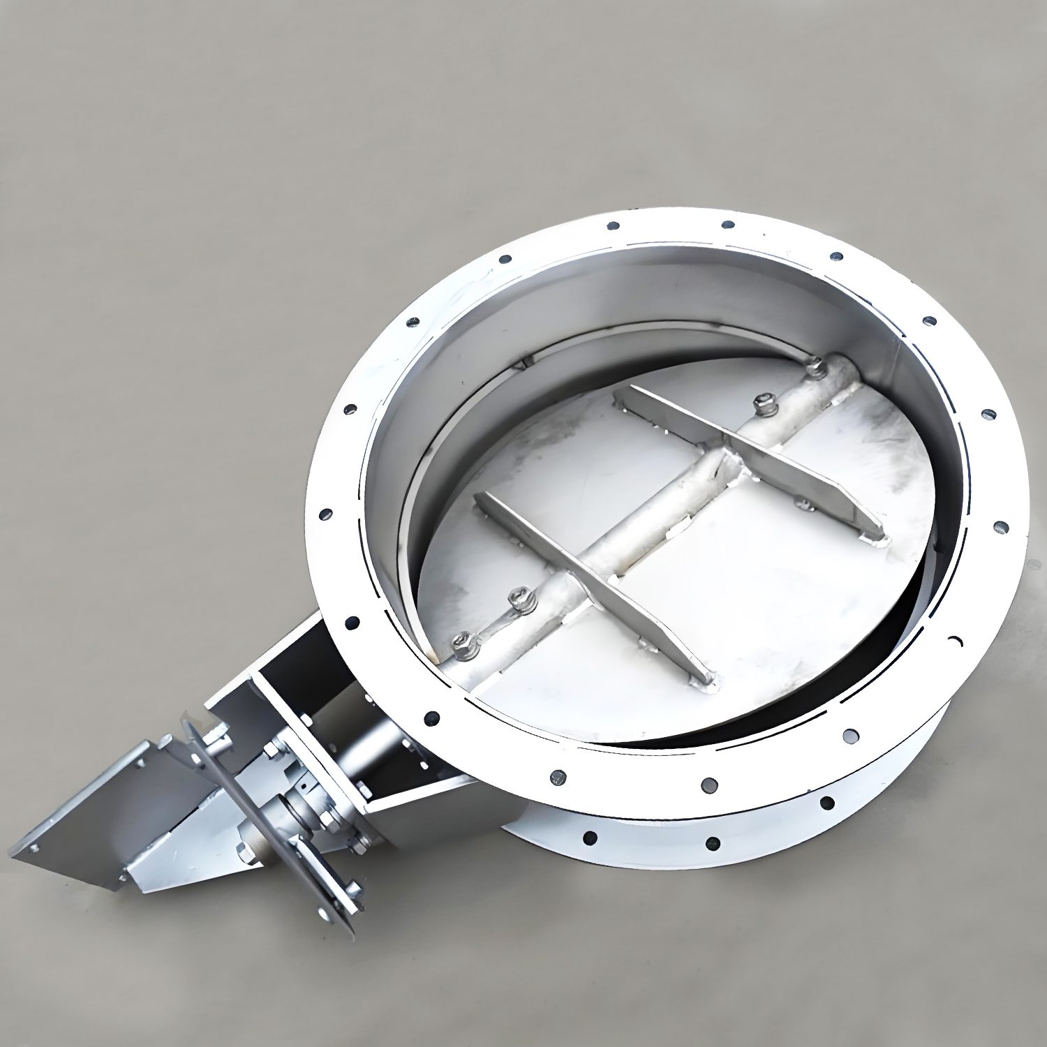
Differences and Applications of On/Off and Regulating Electric Butterfly Valves
2024-12-20
News
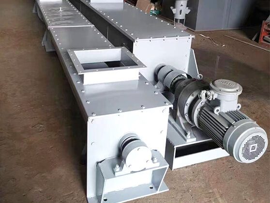
U-type Screw Conveyor: Efficient Transport Solution
2024-12-19
News
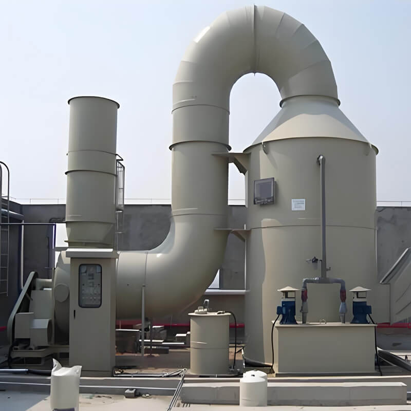
Corrosion Causes and Prevention in Flue Gas Desulfurization Systems
2024-12-18
News
Maintenance Guide for Clinker Bulk Loader
2024-12-17
News
Boiler Bag Dust Collector Renovation Case
2024-12-16
News
How to Effectively Handle Workshop Dust?
2024-12-13
Page
1
Page
2
Page
3
Page
4
Page
5
Do You Want To Boost Your Business?
drop us a line and keep in touch
Contact Us
English
English
Russian
French
Portuguese
Arabic
Spanish
Japanese
English
English
Russian
French
Portuguese
Arabic
Spanish
Japanese
WhatsApp us