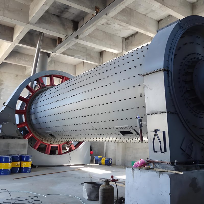
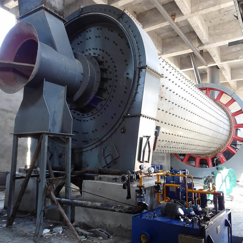
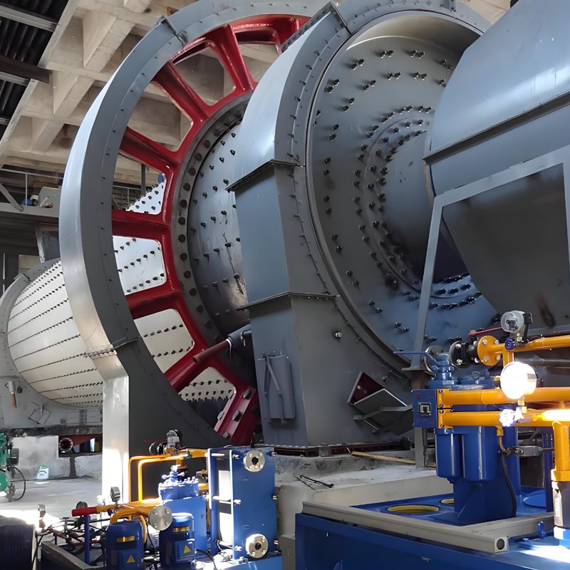
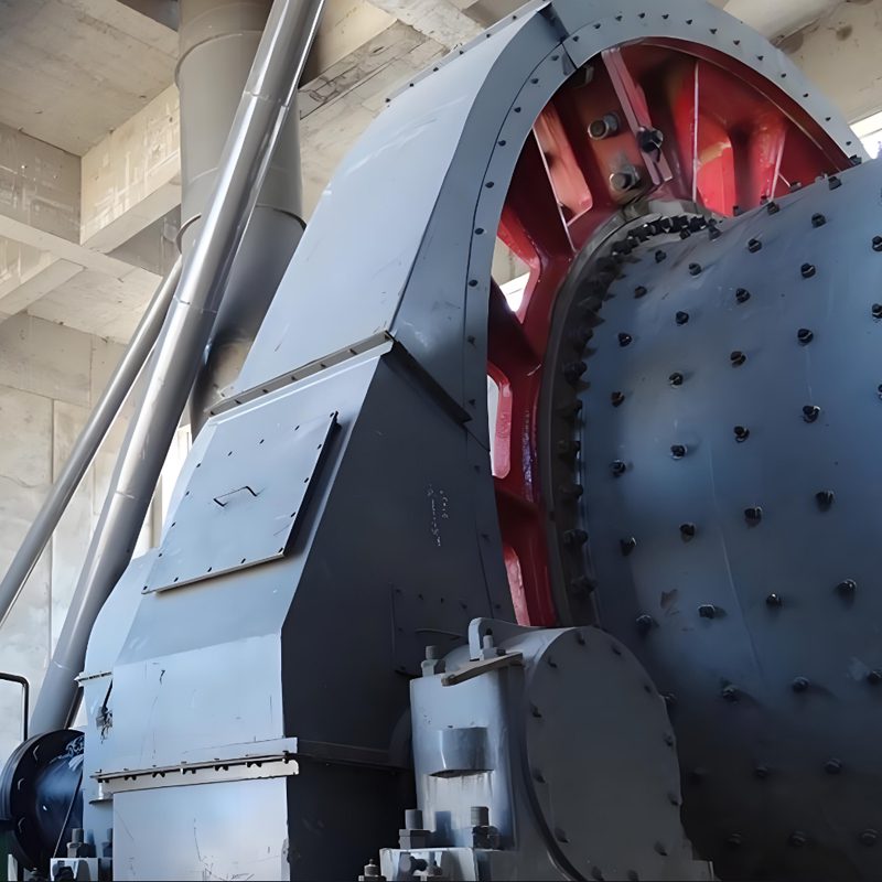
As a professional cement equipment manufacturer, Darko has accumulated years of experience in the technical research, development, and manufacturing of large cement machinery, including the cement ball mill, establishing a mature production system and excellent technical reserves.
カスタマイズ・ソリューション
Based on the grinding system used by our customers, we can customize and optimize the ball mill. Whether it is an open-circuit grinding system, a closed-circuit grinding system, or a combined grinding system with a roller press, our engineering team will design a reasonable solution according to user needs, providing the most suitable ball mill.
Complete Cement Grinding Station
In addition to cement ball mills, Darko also provides cement silos, which are ideal for storing and managing cement, ensuring a smooth production process. If you need more than just a cement ball mill, Darko can provide a complete cement grinding station design and construction service. We will provide comprehensive technical support and solutions based on your project needs.
The cement ball mill is essential for crushing materials after initial breakage. This grinding mill utilizes a specific number of steel balls as grinding media within its cylinder.
01. Multiple Feeding Device Options
Darko has designed three configurations of feeding devices: drum feeders, combined feeders, and feeding trolleys.
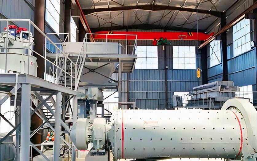
Drum Feeder
- The specially designed anti-spillage cone effectively addresses material leakage issues.
- Materials are gradually pushed into the feed inlet by a spiral plate, achieving forced feeding.
- Suitable for use with single-screw classifiers or hydrocyclones, it features a simple structure that is easy to use and requires no maintenance.
Combined Feeder
- Maintains high-level feeding without backflow or overflow, reducing labor intensity and preventing contamination while improving efficiency.
- Ideal for use with double-screw classifiers.
Feeding Trolley
- The specially designed anti-spillage cone effectively addresses material leakage issues.
- Connects via a flange to the feeding device (hopper or feeder).
- Features a simple structure and easy maintenance; suitable for large mills of 32 and above.
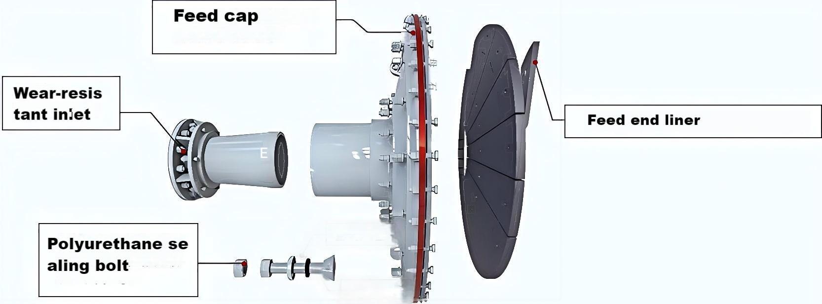
02. Various configurations in the feed section extend service life
03. Cylinder Design
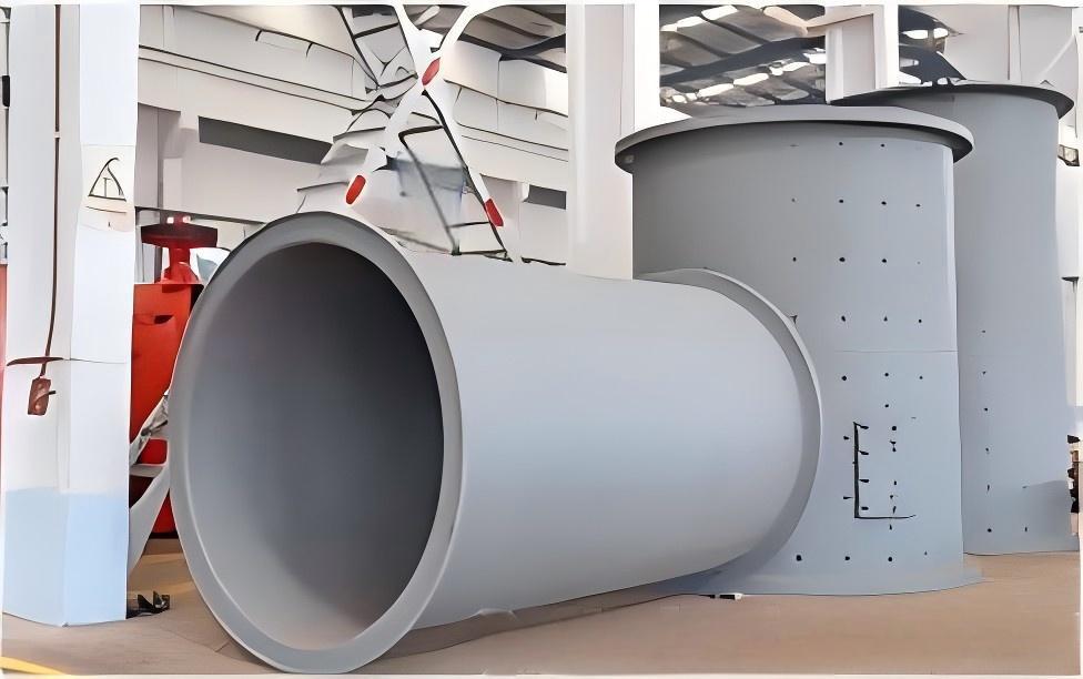
The cylinder features submerged arc automatic welding and internal liners to protect the cylinder.
Cylinder
- The cylinder is made of thick steel plates.
- It features submerged arc automatic welding, ensuring high quality and an attractive appearance.
- Flange plates are connected at both ends to the cast steel inlet (outlet) end covers.
Combined Feeder
- Internally installed to protect the inner wall of the cylinder and control the movement of steel balls within.
- High Manganese Steel (ZGMn13): Cast using lost foam casting, offering fast installation and high precision.
- High Chromium Cast Iron Liners: Chromium content exceeds 11%, with a chromium-to-carbon ratio over 4.5.
- Rubber Liners: Made with a steel membrane and vulcanized using styrene-butadiene or natural rubber, with an Akron abrasion of 0.14 cm³/1.6 km.
04. Large and Small Gear Spray Lubrication System
Large and Small Gears
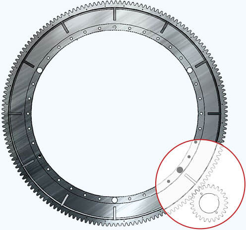
- The large gear features an open gear design, made from ZG310-570 cast material.
- The small gear is forged from 45# steel, with high-frequency quenching on the teeth, ensuring high manufacturing precision and smooth transmission.
- This setup produces low noise and has a long service life.
Spray Lubrication System
- The primary modes of damage and failure in mill gears are wear, adhesion, and pitting, mainly caused by poor lubrication. Therefore, it is recommended to install a spray lubrication system for large and small gears (required for ball mills above 27).
- The lubrication device is specifically designed for the large and small gears. It uses compressed air to atomize and spray dry oil or dilute oil onto the load-bearing tooth surfaces, forming a fine and uniform layer of dry oil. This significantly reduces friction and achieves energy-saving benefits. As shown in the image, when an oil film forms, it operates in a liquid friction zone, resulting in reduced friction.
05. Rolling Bearing Replacing Sliding Bearing
The bearings use double-row self-aligning roller bearings instead of sliding bearings. These bearings feature labyrinth seals, allowing for linear contact, which significantly reduces friction compared to the surface contact of sliding bearings.
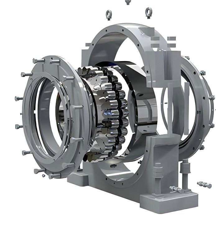
For each model of cement ball mill, a simulation analysis of stress, relative displacement, deformation shape, and safety factor will be conducted to determine whether the bearing model meets the specifications required for that particular ball mill.
06. Multiple Discharge Options
Grate Type
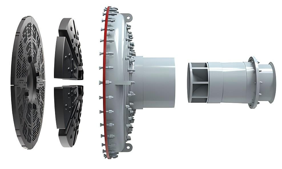
The grate-type ball mill is unique and serves to force the discharge of ore, making it suitable for coarse grinding operations or primary grinding stages.
Overflow Type
The discharge end cover and liners of the overflow mill are the same as those at the feed end.
07. Slow Drive System and Transmission
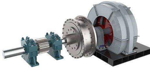
Mill Drive Section (Asynchronous Motor Drive)
The asynchronous motor drive is suitable for mills under 400 kW, using high starting torque squirrel-cage or wound asynchronous motors.
Synchronous Motor Drive Section
The synchronous motor drive is designed for ball mills above 400 kW, utilizing a dedicated TDMK low-speed synchronous motor. It connects to the pinion shaft through a pneumatic clutch, achieving single-stage reduction transmission to drive the cylinder rotation.
The pneumatic clutch enables segmented starting of the motor and main machine (“soft start”), improving starting conditions and providing overload protection.
Slow Drive System
The slow drive system facilitates maintenance and liner replacement for the ball mill. When the mill shuts down for over 4 hours, material can solidify inside the cylinder, making startup difficult. Before starting the main motor, the operator uses the slow drive to rotate the cylinder, loosening the material to assist with the main motor startup.
08. Variable Frequency Control Cabinet
Frequency Sensitive Resistor Cabinet and Variable Frequency Cabinet
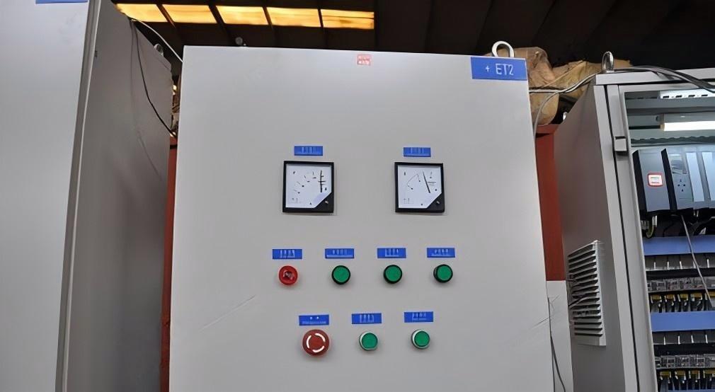
When the motor starts directly, the output torque of the shaft and the stator current vary. Using a wound motor, the frequency-sensitive starting cabinet or liquid resistance starting cabinet achieves reduced voltage starting, minimizing the impact on the power grid and controlling the current and torque changes during startup.
Advantages
- Electrical Protection: The resistor cabinet reduces the impact on the power grid during startup.
- Mechanical Protection: The hydraulic coupler or pneumatic clutch protects the motor.
09. Hydraulic Lifting Device
Cylinder, feed inlet, discharge outlet. This device facilitates easy and quick maintenance operations for the mill's bearing components, resulting in low operating costs.
The hydraulic lifting device mainly consists of hydraulic jacks and a hydraulic station system. During maintenance, operating the hydraulic station's handle allows the hydraulic jacks to raise and lower as needed.
10. Equipped with Integral Frame
Method One
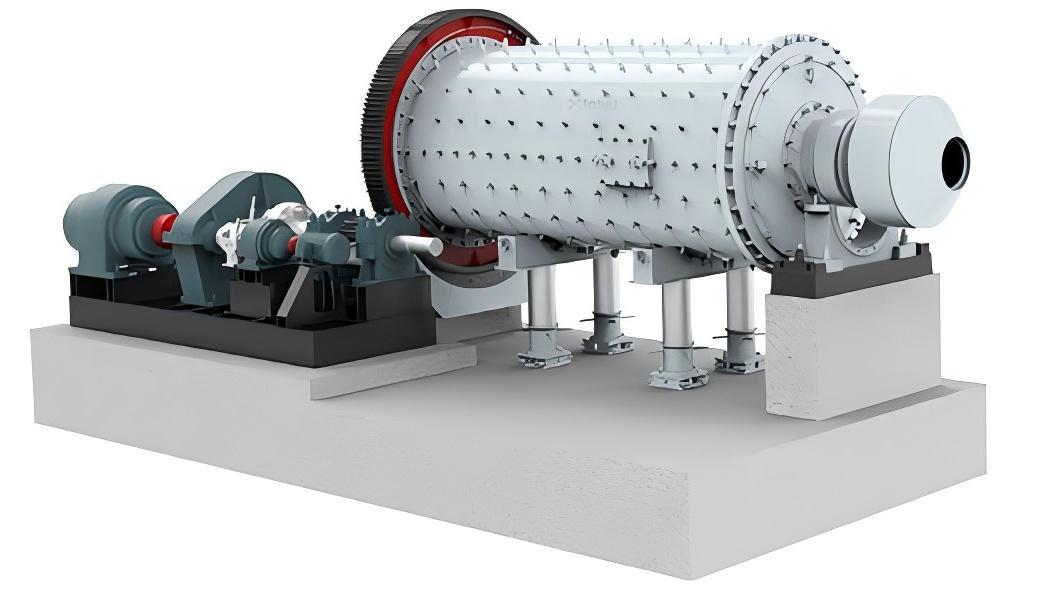
For medium and small cement ball mill, Darko Mining Equipment uses an integral frame design. The entire mill is installed on a single welded frame, allowing for installation and debugging within the factory. Once on-site, it can be placed on a pre-prepared foundation, leveled, and securely installed. This approach significantly reduces the installation workload, shortens the construction period, and facilitates long-distance transportation of the equipment.
Method Two
The non-integral frame installation method is suitable for the installation of large mills.
11. Application
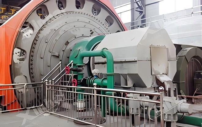
The cement ball mill serves a variety of industries, including cement, silicate products, new building materials, refractory materials, fertilizers, and both black and non-ferrous metal beneficiation. It efficiently performs dry or wet grinding of various ores and other grindable materials.
It is suitable for grinding various ores and materials, making it popular in mineral processing, building materials, and chemical sectors.
12. Working Principle
This cement ball mill operates as a cylindrical rotating device with external gear transmission. It consists of two bins and a grid-type ball mill.
Materials are fed evenly into the first bin through a hollow shaft in the feed device. This bin features a stepped or corrugated lining, filled with steel balls of different sizes. As the cylinder rotates, centrifugal force lifts the steel balls to a height. They then fall and create a strong impact, grinding the material.
Once the material is roughly ground in the first bin, it moves through a partition board into the second bin. This bin has a flat lining board and contains more steel balls for further grinding. Finally, the powder is discharged through the grate plate, completing the grinding operation.

