
Overview
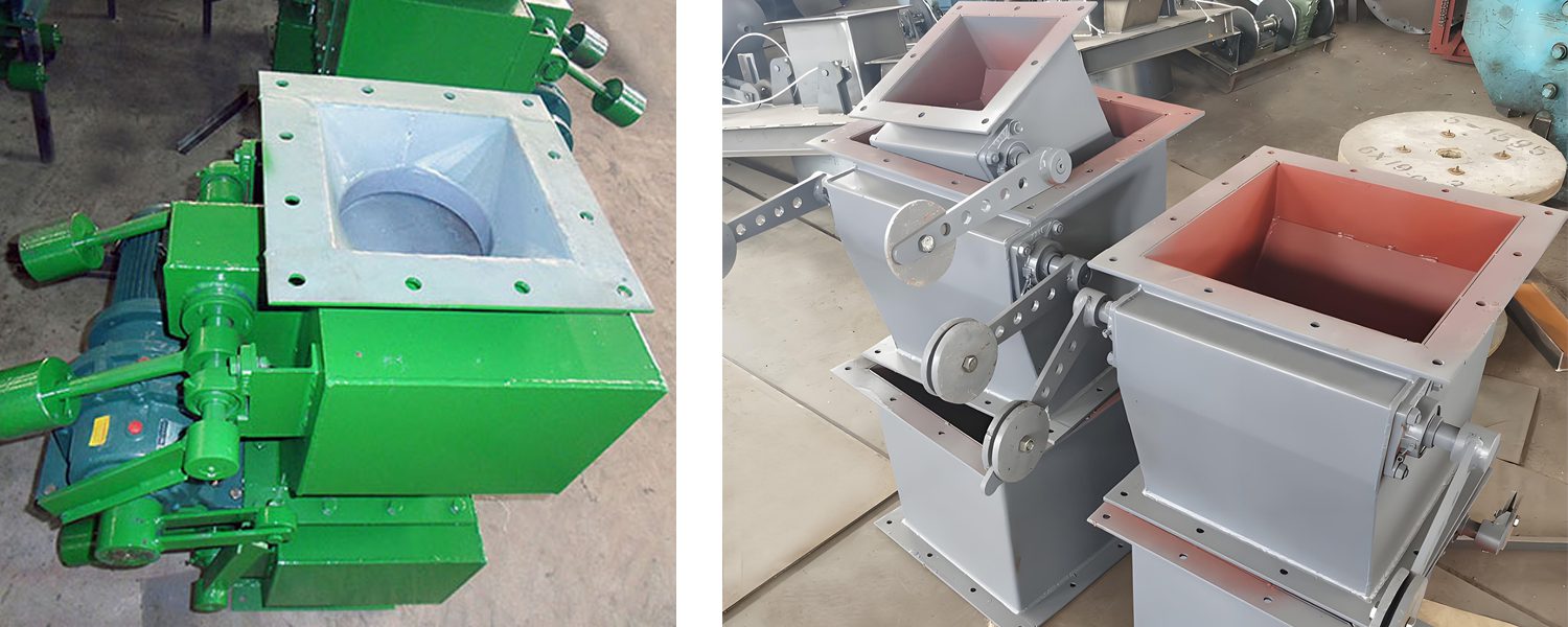
The airlock flap valve is a device that automatically discharges ash using the weight of the material. It features through ash discharge, good sealing, lightweight, simple structure, and quick action. The airlock flap valve typically features a double-layer structure. By alternately opening and closing the upper and lower valves, it ensures the prevention of air leakage.
It is widely used in industries such as metallurgy, chemical engineering, power generation, light industry, building materials, construction, mining, cement, grain, food, and other industrial applications.
What types of airlock flap valve does darko offer?
1. Circular type of single door

| DN | D | D1 | H | L | n-d | Weight(kg) |
| 100 | 176 | 140 | 290 | 390 | 6 φ11 | 29 |
| 150 | 226 | 190 | 290 | 420 | 6 φ11 | 37 |
| 200 | 290 | 250 | 350 | 495 | 8 φ11 | 51 |
| 220 | 300 | 365 | 350 | 505 | 8 φ11 | 63 |
| 250 | 340 | 300 | 350 | 570 | 12 φ13 | 94 |
| 300 | 390 | 350 | 380 | 600 | 12 φ13 | 175 |
| 320 | 410 | 370 | 380 | 610 | 12 φ13 | 236 |
| 400 | 490 | 450 | 450 | 700 | 16 φ13 | 396 |
| 450 | 540 | 500 | 450 | 715 | 16 φ13 | 473 |
| 500 | 600 | 560 | 450 | 715 | 16 φ13 | 546 |
2. Rectangular type of single door

| A1×A | K×B1 | m×B | C1×C | H | L | n-d | Weight(kg) |
| 100×100 | 2×72.5 | 2×72.5 | 180×180 | 290 | 390 | 8φ11 | 29 |
| 150×150 | 2×100 | 2×100 | 240×240 | 290 | 420 | 8φ11 | 37 |
| 200×200 | 2×125 | 2×125 | 290×290 | 350 | 495 | 8φ11 | 51 |
| 300×200 | 3×125 | 2×125 | 400×290 | 380 | 600 | 10φ13 | 94 |
| 300×300 | 3×120 | 3×120 | 400×400 | 380 | 600 | 12φ13 | 175 |
| 400×200 | 4×115 | 2×125 | 500×290 | 400 | 700 | 12φ13 | 230 |
| 400×300 | 4×115 | 3×120 | 500×400 | 400 | 700 | 14φ13 | 285 |
| 400×400 | 4×115 | 4×115 | 500×500 | 400 | 700 | 16φ13 | 346 |
| 500×400 | 5×112 | 4×115 | 600×500 | 450 | 735 | 18φ13 | 378 |
| 500×500 | 5×112 | 5×112 | 600×600 | 450 | 735 | 20φ13 | 465 |
3. Circular type of two doors

| DN | D1 | D | L | H | n-d | Weight(kg) |
| 400 | 450 | 490 | 1280 | 400 | 16 φ13 | 346 |
| 450 | 500 | 540 | 1280 | 400 | 16 φ13 | 418 |
| 500 | 560 | 600 | 1410 | 450 | 16 φ13 | 505 |
| 550 | 610 | 650 | 1410 | 450 | 16 φ13 | 583 |
| 600 | 660 | 700 | 1410 | 500 | 20 φ13 | 652 |
| 650 | 710 | 750 | 1410 | 500 | 20 φ13 | 705 |
| 700 | 760 | 800 | 1520 | 500 | 24 φ13 | 755 |
| 750 | 810 | 850 | 1520 | 600 | 24 φ13 | 803 |
| 800 | 860 | 900 | 1610 | 600 | 24 φ18 | 841 |
4. Rectangular type of two doors

| A1×A | K×B1 | C1×C | m×B | L | H | n-d | Weight(kg) |
| 400×400 | 4×115 | 500×500 | 4×115 | 1400 | 400 | 16 φ13 | 346 |
| 500×400 | 4×140 | 600×500 | 4×115 | 1470 | 400 | 16 φ13 | 378 |
| 500×500 | 4×140 | 600×600 | 4×140 | 1470 | 400 | 16 φ13 | 464 |
| 600×400 | 5×132 | 700×500 | 4×115 | 1470 | 400 | 18 φ13 | 525 |
| 600×500 | 5×132 | 700×600 | 4×140 | 1470 | 600 | 18 φ13 | 561 |
| 600×600 | 5×132 | 700×700 | 5×132 | 1470 | 600 | 20 φ13 | 608 |
| 700×400 | 5×152 | 810×510 | 5×92 | 1520 | 600 | 20 φ13 | 649 |
| 700×500 | 5×152 | 810×610 | 5×112 | 1520 | 600 | 20 φ13 | 703 |
| 700×600 | 5×152 | 810×710 | 5×132 | 1520 | 600 | 20 φ 13 | 723 |
| 700×700 | 5×152 | 810×810 | 5×152 | 1520 | 600 | 20 Φ13 | 764 |
| 800×500 | 6×144 | 920×620 | 5×93 | 1620 | 600 | 22 φ18 | 808 |
| 800×600 | 6×144 | 920×720 | 5×133 | 1620 | 600 | 22 φ18 | 841 |
| 800×700 | 6×144 | 920×820 | 5×153 | 1620 | 600 | 22 φ18 | 885 |
| 800×800 | 6×144 | 920×920 | 6×144 | 1620 | 600 | 24 φ18 | 932 |
| 900×600 | 7×137.9 | 1020×720 | 5×133 | 1730 | 600 | 24 φ18 | 995 |
| 900×700 | 7×137.9 | 1020×820 | 5×153 | 1730 | 600 | 24 φ18 | 1040 |
| 900×800 | 7×137.9 | 1020×720 | 6×144 | 1730 | 600 | 26 φ18 | 1100 |
| 1000×600 | 7×152.9 | 1135×720 | 6×110.8 | 1810 | 675 | 26 Φ24 | 1170 |
| 1000×700 | 7×152.9 | 1135×835 | 6×128.3 | 1810 | 675 | 26 Φ24 | 1230 |
| 1000×800 | 7×152.9 | 1135×935 | 7×152.9 | 1810 | 675 | 28 Φ24 | 1300 |
How does an airlock flap valve work?
The working principle of the airlock flap valve mainly relies on its unique structure and mechanical transmission mechanism to effectively prevent air leakage during material transport.
♦Mechanical Transmission for Opening and Closing
The airlock flap valve uses a mechanical transmission mechanism to open and close the upper and lower valves. This mechanism usually includes components like linkages and cranks, allowing the valves to open and close in a preset manner through their interactions.
♦Automatic Reset Mechanism
To ensure the reliable resetting of the valve plate and prevent drafts from entering, the airlock flap valve is equipped with an automatic reset mechanism, such as a lever system or tension spring. These mechanisms can physically reset the valve plate after it closes, maintaining the system’s sealing.
♦Prevention of Air Leakage
The design of the airlock flap valve aims to maintain the system’s sealing during material transport. It prevents air from entering or escaping through the valve. This is important because air leakage could affect the quality and efficiency of material transport. The upper and lower valves operate alternately. This, along with the automatic reset mechanism, enables effective fluid control. As a result, it achieves speed regulation and prevents air leakage.
♦Materials and Drive Methods
The airlock flap valve can be made from various materials. It can also use different drive methods to suit different working environments and material characteristics. Common materials include stainless steel and carbon steel. The drive methods can be electric, pneumatic, or gravity-operated. This versatility meets the needs of various industrial applications.
Advantages & Highlights of Darko’s airlock falp valve
♦Simple Structure
It has a straightforward design, making it easy to maintain and clean. This helps ensure the flow and cleanliness of the medium.
♦Lightweight Operation
The valve can be operated with minimal force, making it suitable for various applications.
♦Good Sealing
It effectively prevents medium leakage, enhancing the safety and stability of the production process.