
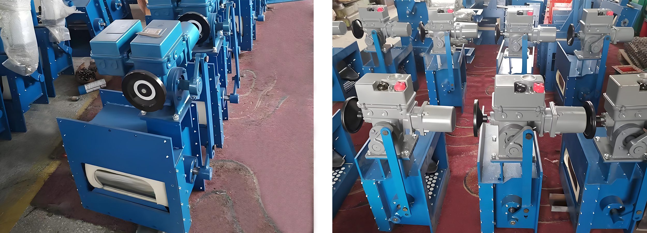
Function of a Motorized flow control gate
The motorized flow control gate mainly plays the role of on-off flow regulation in the flow transportation control system of powder, grain materials and small particle materials. It adopts foreign advanced technology and is specially used for the unloading production of raw material homogenization warehouse and cement warehouse. Equipment, the driving device of this product is an adjustable electric actuator. The opening is automatically adjusted by inputting a 4~20m .A control signal to realize the adjustment function.
Performance characteristics
1. Reasonable and compact structure, sensitive action, no jamming, easy installation and use; low noise, small vibration, easy maintenance and other characteristics.
2. The driving device is an adjustable electric actuator, which can realize the flow adjustment function and has high flow adjustment accuracy.
3. The valve core is made of high-performance wear-resistant materials, and the surface is plated with hard chromium to achieve high smoothness and wear resistance; the opening is arc-shaped to make the material flow smoothly. The valve core seal is made of high-quality high-density felt and closely fits the arc outer surface. The tightness of the valve core and the felt can be adjusted to achieve no leakage.
Working principle
The motorized flow control gate can realize opening, closing and regulating functions in the 4~20mA signal. When the 4mA control signal is input to the electric actuator, the valve is in a fully closed state.
When the 20mA control signal is input to the electric actuator, the valve reaches the fully open state. The electric actuator is in the adjustment state under the action of 4~20mA control signal, and can adjust the valve opening with any given signal value, thereby realizing the valve adjustment function.
For more information or technical inquiries, please feel free to contact us. We are happy to assist you.
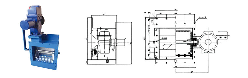
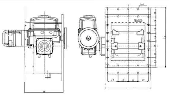
Structure selection parameters
| Unit |
B200 |
B250 |
B300 |
B400 |
B500 |
B630 |
B800 |
|
| Flow range | m³/h |
40-260 |
60-360 |
70-480 |
90-650 |
10-820 |
140-1450 |
160-1600 |
| circulation area | m² |
0.012 |
0.014 |
0.017 |
0.026 |
0.032 |
0.051 |
0.073 |
| Power supply | V |
AC38050Hz (can be determined according to customer requirements) |
||||||
| corner | θ° |
0~90 |
||||||
| input signal | mA |
4~20 |
||||||
| Feedback signal | mA |
4~20 |
||||||
| breathable area | m² |
0.057 |
0.064 |
0.07 |
0.09 |
0.13 |
||
| Air consumption | m³/min |
0.4 |
0.5 |
0.6 |
0.7 |
|||
| Traffic characteristics |
|
Straight line or equal percentage |
||||||
| action time |
|
30s |
||||||
| Operating temperature |
|
≤180℃ |
||||||