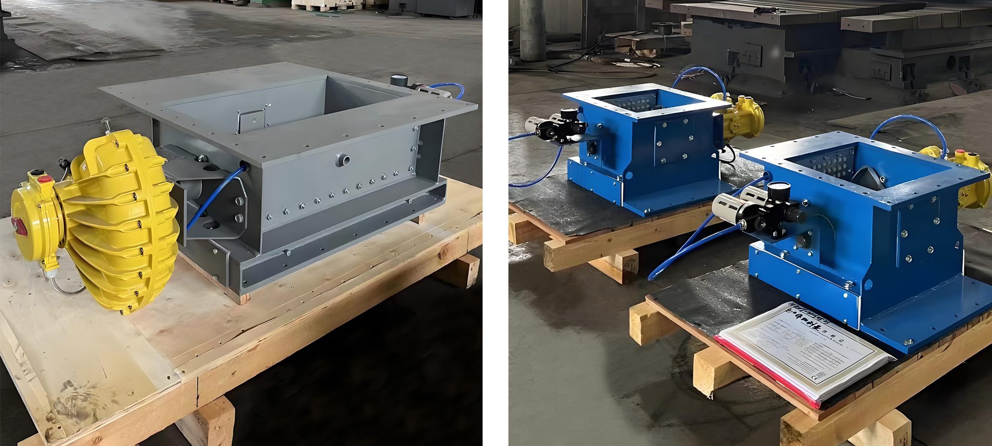
Pneumatic flow control gate mainly plays a role of switching and regulating flow in powder and liquid conveying control systems, granular and small particle materials.
Darko uses advanced foreign technology specifically designed for the unloading production of raw material homogenization silos and cement silo equipment. The driving device of this product adopts fan-shaped cylinders (120-100) and positioners (6DR5020-0NG0O-OAAO) to realize the valve flow regulation function. It is an ideal device for regulating the flow size. It automatically adjusts the opening by inputting 4~20mA control signals to realize the regulation function.
Performance characteristics
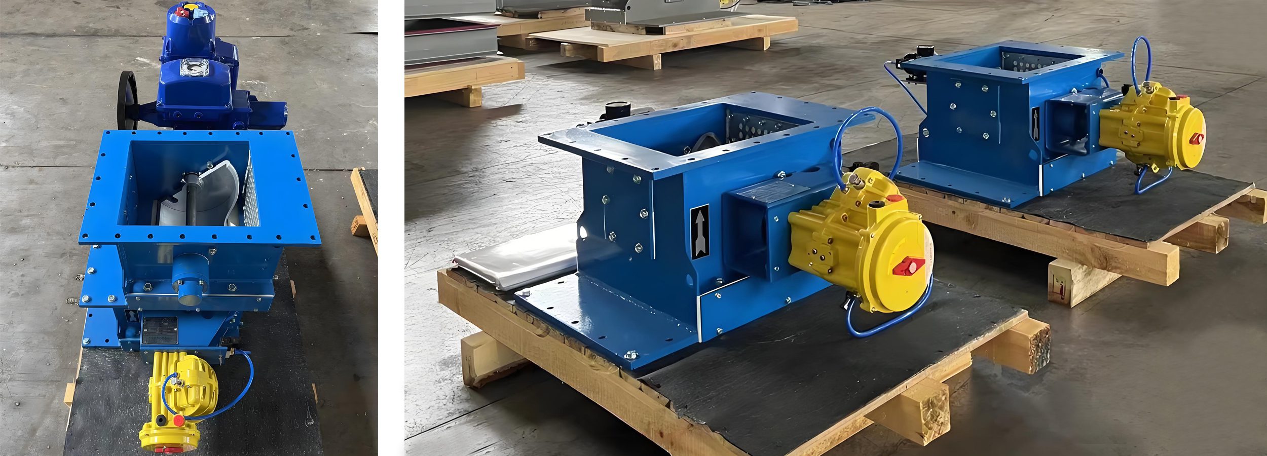
1. The design features a reasonable and compact structure that ensures sensitive action without jamming. It allows for easy installation and use, while also operating with low noise and small vibration, making maintenance straightforward.
2. The driving device consists of a fan-shaped cylinder and a positioner, enabling effective flow regulation.
3. The valve core is constructed from high-performance wear-resistant material, with a hard chrome-plated surface that provides a high finish and excellent wear resistance. Its arc-shaped opening ensures smooth material flow.
The valve core seal uses high-quality, high-density felt that fits tightly against the arc outer surface. Users can adjust the tightness between the valve core and the felt to achieve a no-leak condition.
Working Principles
The pneumatic flow control gate can realize the opening, closing and regulating functions under the 4-20mA signal. When the electric actuator receives a 4 mA control signal, it positions the valve in the fully closed state. When it receives a 20 mA control signal, the actuator opens the valve completely. Under the influence of the 4-20 mA control signal, the actuator maintains the valve in a regulating state, allowing for adjustments to the valve opening based on any given signal value. This process enables the valve regulation function.
For more information or technical inquiries, please feel free to contact us. We are happy to assist you.
Structural selection parameters
| project
Specification |
Unit |
B200 | B250 | B300 | B400 | B500 | B630 | B800 |
| Flow range | m³/h | 40-260 | 60-360 | 70-480 | 90-650 | 10-820 | 140-1450 | 160-1600 |
| Circulation area | m² | 0.012 | 0.014 | 0.017 | 0.026 | 0.032 | 0.051 | 0.073 |
| Power supply | V | AC38050Hz (can be determined according to customer requirements) | ||||||
| Corner | θ° | 0~90 | ||||||
| Input signal | mA | 4~20 | ||||||
| Feedback signal | mA | 4~20 | ||||||
| Breathable area | m² | 0.057 | 0.064 | 0.07 | 0.09 | 0.13 | ||
| Air consumption | m³/min | 0.4 | 0.5 | 0.6 | 0.7 | |||
| Traffic characteristics | Straight line or equal percentage | |||||||
| Action time | 30s | |||||||
| Operating temperature | ≤180℃ | |||||||
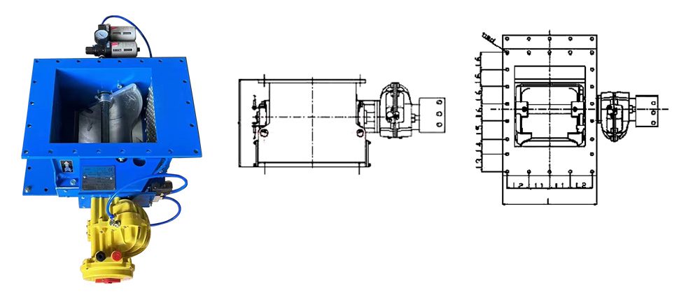
Drawing