
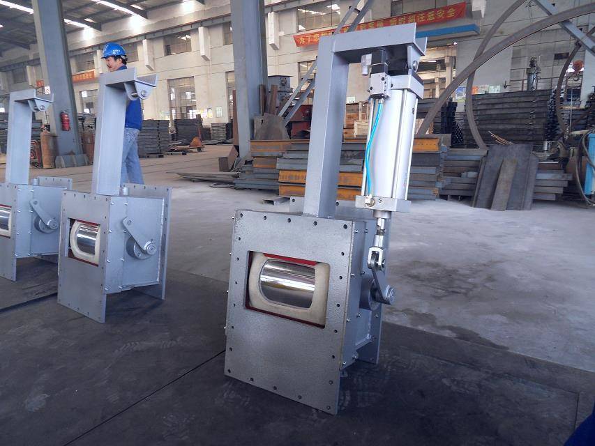
The pneumatic on off valve is powered by a cylinder to achieve its switching function.
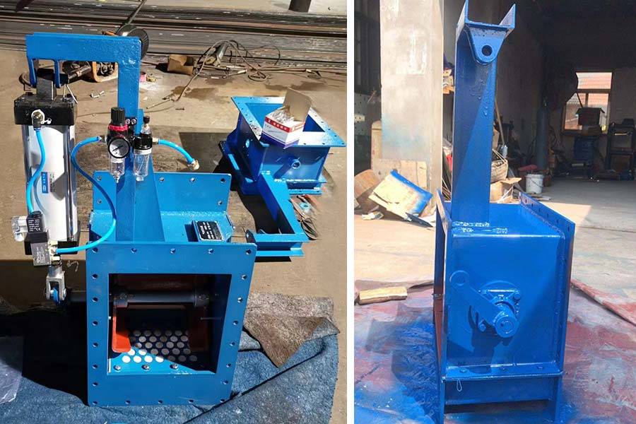
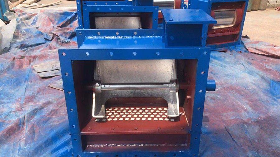
In terms of structure, there is no significant difference between the valve body of a pneumatic on-off valve and that of an electric switching control gate. The main difference lies in the driving forces that change the valve position.
The pneumatic on-off valve is driven by control air in the air circuit, which acts on the operating cylinder in the valve. This pressure pushes the piston to move, driving the slider to change the valve position.
In contrast, the electric flow control gate generates electromagnetic suction through a spiral coil, which drives the slider to change the valve position of the valve body.
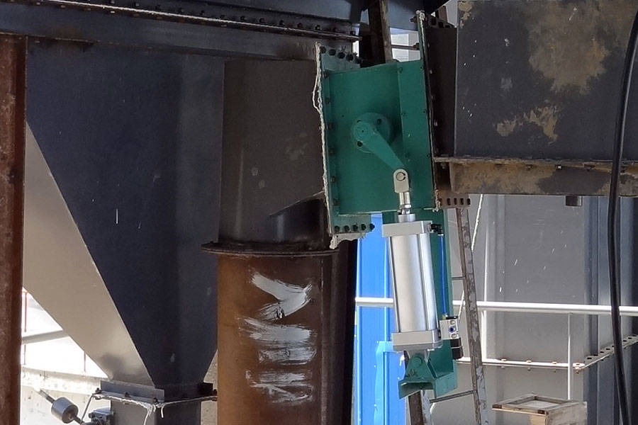
The pneumatic switch control gate changes its position by controlling the air in its cylinder to create a certain pressure. This pressure then pushes the piston and slider to change the valve position. As a result, the actual control speed is relatively slow.
In contrast, the electric flow control gate generates suction force at a relatively fast speed. Therefore, from the perspective of working speed, the electric switch control gate operates faster.
In addition, the control signal connected to the pneumatic switch control gate is a pressure signal. This signal must be connected with a pipe and requires a large volume.
In contrast, the control signal of electric switching valves is generally a current signal. This signal can be connected by wires, and there is no operating plunger. Therefore, the volume of the electric flow control gate is smaller than that of pneumatic switch control gates.
Specification
| project
Specification |
Unit |
B200 | B250 | B300 | B400 | B500 | B630 | B800 |
| Flow range | m³/h | 40-260 | 60-360 | 70-480 | 90-650 | 10-820 | 140-1450 | 160-1600 |
| Circulation area | m² | 0.012 | 0.014 | 0.017 | 0.026 | 0.032 | 0.051 | 0.073 |
| Power supply | V | AC38050Hz (can be determined according to customer requirements) | ||||||
| Corner | θ° | 0~90 | ||||||
| Input signal | mA | 4~20 | ||||||
| Feedback signal | mA | 4~20 | ||||||
| Breathable area | m² | 0.057 | 0.064 | 0.07 | 0.09 | 0.13 | ||
| Air consumption | m³/min | 0.4 | 0.5 | 0.6 | 0.7 | |||
| Traffic characteristics | Straight line or equal percentage | |||||||
| Action time | 30s | |||||||
| Operating temperature | ≤180℃ | |||||||
Drawing & Datas
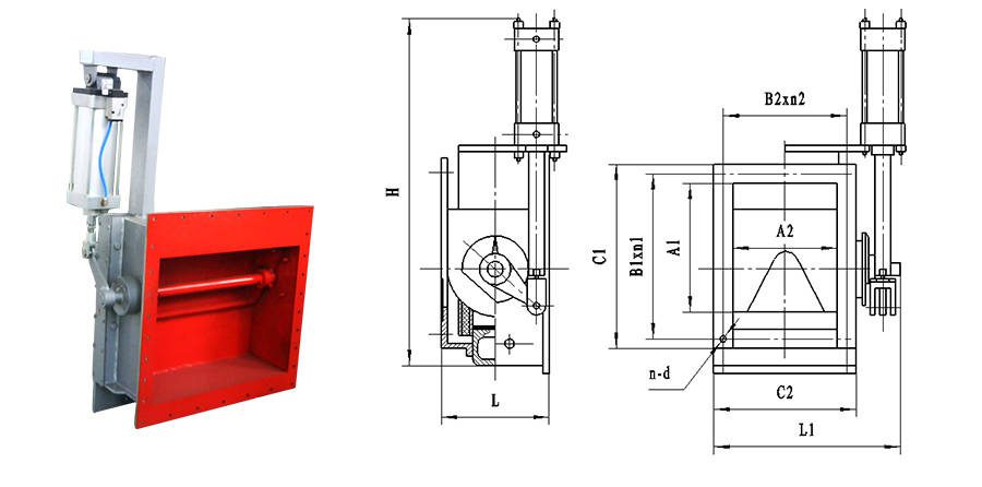
| Specification | L | La | n*L1 | L2 | L3 | L4 | L5 | n*L6 | n*d | H |
| B250 | 340 | 520 | 1*100 | 100 | 72 | 63 | 75 | 4*70 | 20*φ12 | 320 |
| B300 | 390 | 520 | 2*85 | 90 | 72 | 63 | 75 | 4*70 | 22*φ12 | 320 |
| B400 | 490 | 520 | 2*110 | 115 | 72 | 63 | 75 | 4*70 | 22*φ12 | 320 |
| B500 | 580 | 590 | 4*90 | 90 | 90 | 75 | 95 | 3*95 | 24*φ14 | 370 |
| B630 | 710 | 620 | 4*110 | 115 | 65 | 76 | 110 | 3*110 | 24*φ14 | 410 |