
Overview
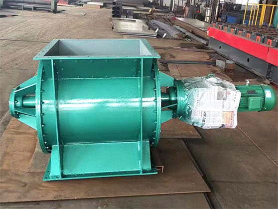
The rotary valve has high processing precision and features a lock-air function. It can be used as a volumetric feeder for pulverized materials in crushing and classification systems, as well as a discharge device in separation and dust collection systems, or in pneumatic conveying systems for both pressure and suction.
It can be made from various materials, including cast iron, cast steel, stainless steel, and titanium steel.
The flange can have various structural forms, such as square or round, to meet different user needs.
How does a rotary valve work?
When the star discharge valve starts operating, materials flow into the star wheel from the inlet. As the star wheel rotates, it pushes the materials into the gaps between the gears. The gears convey the materials to the outlet. When the materials reach the outlet, the system forcibly discharges them. This allows the materials to flow to the next processing step. As the materials in the upper hopper fall by gravity, they fill the gaps between the blades. The system discharges them from the bottom as the blades rotate. Therefore, the star discharge valve achieves quantitative and continuous discharging. Each gear follows its own independent motion path and speed. This enables quick and uniform material transfer. Additionally, operators can adjust the speed and direction of the star wheel as needed. This accommodates specific material conveying requirements.
Application
The star discharge valve can be used in material collection systems as a discharge device for hoppers. It is currently one of the most advanced discharge devices in the country, commonly used in dust collection systems as one of the essential components.
It is particularly suitable for dust and small particle materials, making it a preferred choice in engineering projects across various industries such as environmental protection, metallurgy, chemical, grain, cement, road construction, and drying equipment.
The temperature of the materials it conveys can reach up to 280°C for the standard type, with a certain isolation between the bearings and the impeller to prevent ultrafine powders from contacting the bearings. The high-temperature type can handle material temperatures up to 500°C, with a chain wheel connection. The reducer and the discharge device housing are kept at a certain distance.
Highlight
- Efficiency: It can achieve continuous and stable material discharge, with adjustable settings to ensure smooth operation of the production line.
- Uniformity: The groove design inside the rotor allows for uniform dispersion and transport of materials, avoiding clumping or agglomeration.
- Flexibility: The star discharge valve can be adjusted and optimized based on the characteristics of different materials to meet different discharge requirements.
- Reliability: Its simple structural design facilitates maintenance, and its strong wear and corrosion resistance improves the equipment’s service life.
How does a reducer work in rotary valve?
- The reducer can lower the rolling inertia. It generally reduces it by the square of the gear ratio. This allows for timely control of start-stop and speed changes.
- The reducer increases torque. This corresponds to an increase in input power. It reduces the power required from the input motor, especially in cases requiring speed adjustment. Generally, motors are more expensive than reducers. This makes the use of a reducer advantageous.
- The reducer protects the motor during operation. It bears large torque. In the case of overload, only the overload amount divided by the gear ratio is transmitted to the motor. Directly connecting the motor could cause damage.
- In cases of significant overload, the reducer is likely to fail first. It only requires replacement of parts to restore functionality, which is relatively low-cost. If the motor fails, repairs take longer and are more expensive.
- When the motor is directly connected to a low-speed load, the current increases significantly. This is to meet the required output torque. It raises the demands on the motor’s heat dissipation and insulation. From an energy-saving perspective, this is undesirable. Using a reducer can mitigate these issues.
For more information or technical inquiries, please feel free to contact us. We are happy to assist you.